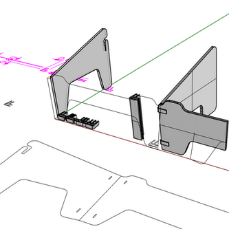
bent-tab rocker
This was a project that I did to investigate "flat-pack" local manufacturing possibilities.
The material used was 14 gauge steel. The digital file (imaged below) was a simple CAD file that allowed for the creation of "bent-tab" connectors during the laser cut process.
The assembly process was intended to be done on delivery. Connecting and truing would be accomplished by bending along cut perforations and mounting the resulting seat to the sides- hammering the bent-tabs would true and secure the seat. Folding the bent-tabs on themselves would lock the connection in place. Images of prototype assembly are included in the gallery below. No glues, connectors, or other material would be needed. Just hammer, block, and safe location to work with assembling.

saddle joint study

This was a quick 3 week exercise to better understand the saddle joint (where your thumb meets your hand). I compared different prototype methods to produce different models with different properties. CNC, 3d print, cast, and vacuum formed.
It was part of a larger project but yielded a great deal of information that I was able to use in teaching.
laptop stand and a stool
I wanted to find a way to teach some of the digital processes by example to sophomores, introducing them to rhino CAD as a design and prototyping workflow in the shop- accessing the Laser cutter, 3d printer, and the CNC machine. I prefer to teach digital tools together so that there is an understanding of appropriateness of process- why to go to one tool over another. Ideally students develop a fluid workflow using both analog and digital when and where appropriate. The goal was for them to be able to play within the frameworks of the tools- back and forth, quickly iterating and prototyping. Below are images of CAD and modeling process.
random steps
This was a project that was used to push the use of a newly acquired CNC machine with experimental work with students. I used Mathematica and Processing to randomly map a given number of steps. After each step, a new decision must be made.. to proceed North, South, East, or West. It is an interesting graphical exercise that starts with very inorganic look and feel, and later approaches produces increasingly organic pattern. I transferred the Processing files to CAD and used these to physically map the steps using a CNC machine. I briefly showed results in a month long exhibit on Broad St in Philadelphia.
beginShape(LINES); // start shape, interpret vertices as lines
walk(width/2, height/2, 5, 0); // make vertices using these four parameters (this is where you would change them)
endShape(); // finish shape
endRaw(); // stop making dxf file
noLoop(); // pause
}
void walk(int x, int y, int val, int cnt){ // val is the step increment
cnt=cnt+1; // counter
if(cnt<500){ // exit function
vertex(x, y, z); // first point
r=random(0, 6); // random switch
if(r>0 && r<=1){ vertex(x+val, y, z); x=x+val; } // new vertex value, which is then saved as the new x, y, or z value
if(r>1 && r<=2){ vertex(x-val, y, z); x=x-val; }
if(r>2 && r<=3){ vertex(x, y+val, z); y=y+val; }
if(r>3 && r<=4){ vertex(x, y-val, z); y=y-val; }
if(r>4 && r<=5){ vertex(x, y, z+val); z=z+val; }
if(r>5 && r<=6){ vertex(x, y, z-val); z=z-val; }
walk(x, y, val, cnt); // recursive function
}
}
void mousePressed(){
loop(); // repeat
}


